Advanced Editing Tools in SGIS: Changing the Drawing Orientation of a Selected Element and Adjusting the Orientation of a Whole Polygon Layer from CW to CCW and Vice Versa with a Single Click Function
Published on: 26.08.2024
Many GIS projects follow specific standards for how geometries should be stored and displayed. Reordering vertices ensures that your data adheres to these standards, facilitating smooth data exchange and interoperability.
Properly ordering vertices ensures topological consistency, maintaining accurate relationships between features such as shared boundaries or connected networks. It also prevents errors that can arise during spatial analysis or when exporting data, ensuring the data remains reliable and usable. In network tracing and flow analysis, the correct vertex order is essential for accurate results. Similarly, GIS operations like buffering or creating offsets rely on the correct orientation of features, and reordering vertices helps achieve the expected outcomes.
For line features like roads, pipelines, or streams, vertex order dictates the line’s direction, which is crucial for accurate network analysis, flow direction modeling, and other spatial analyses.
In many GIS systems, polygons must have their exterior rings drawn in a specific direction (typically clockwise) and interior rings (holes) in the opposite direction (typically counterclockwise).
Changing the orientation of a layer from clockwise (CW) to counterclockwise (CCW), or vice versa, is crucial in GIS to ensure that data meets the specific orientation requirements of different software and data standards.
For instance, the commonly used shapefile format in GIS typically requires polygon rings to have a clockwise (CW) orientation for exterior boundaries and a counterclockwise (CCW) orientation for interior boundaries (holes). This distinction is important for correctly interpreting and displaying polygons.
In contrast, the GML (Geography Markup Language) format usually requires the opposite orientation: counterclockwise (CCW) for exterior boundaries and clockwise (CW) for interior boundaries, following the “right-hand rule” used in many systems.
Having a tool that can adjust the orientation of an entire layer is therefore extremely useful. It helps ensure that spatial data is consistently interpreted and displayed across different platforms, preventing errors and maintaining data integrity.
Incorrect vertex ordering can lead to polygons rendering incorrectly, appearing inside-out, or causing errors in area calculations.
To demonstrate how easy and effective this function is in SGIS v.R, we’ll use two real-world examples.
By following these steps in SGIS v.R, you can efficiently reorder vertices and maintain the accuracy and consistency of your spatial data:
A practical example #1
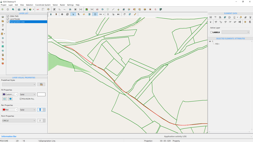
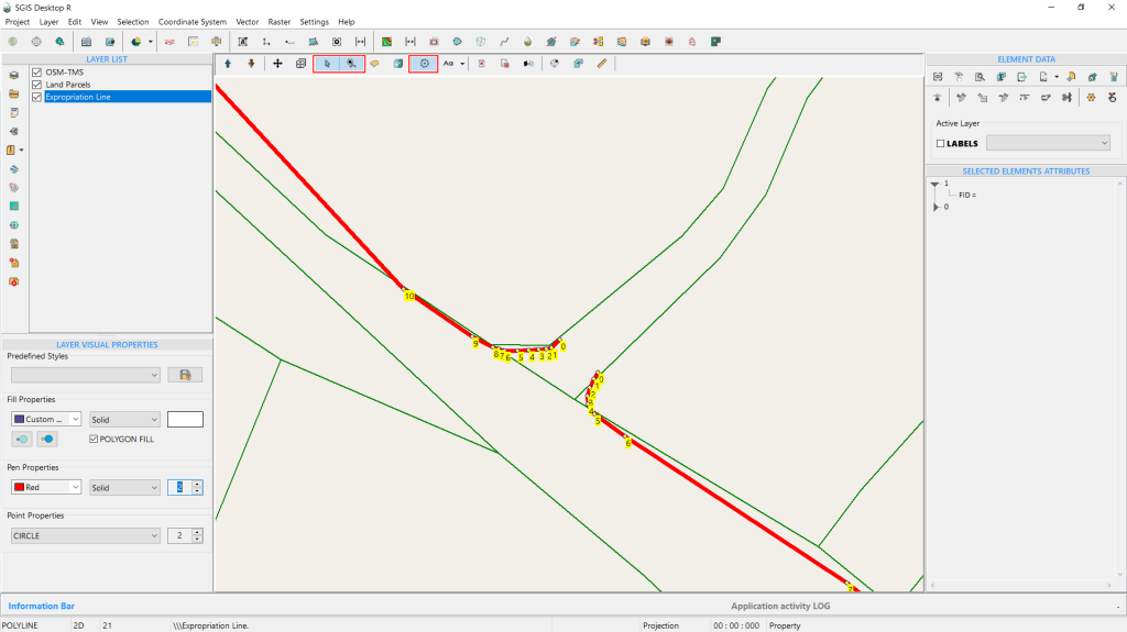
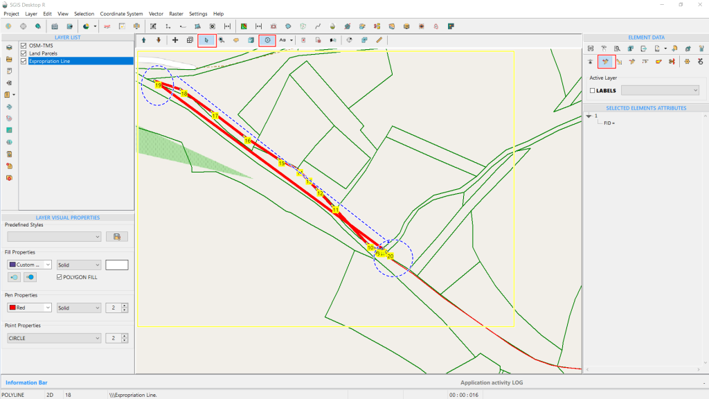
Fig. 1 Sample Data Loaded in SGIS v.R
Our example features GIS data with polygons representing land parcels and two separate polylines that need to be connected.
To achieve this, we must add an additional vertex and snap it to the starting vertex of the second line.
While this is a straightforward task, the challenge arises because both lines begin at the same point but extend in opposite directions.
This scenario highlights the need for a tool that can easily and effectively address such issues.
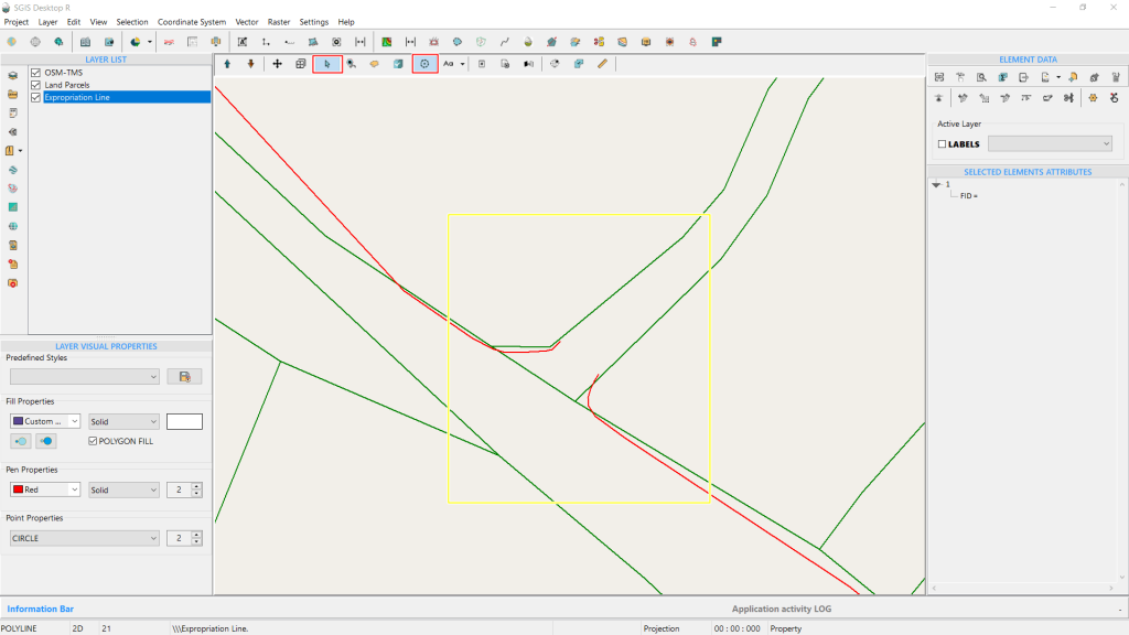
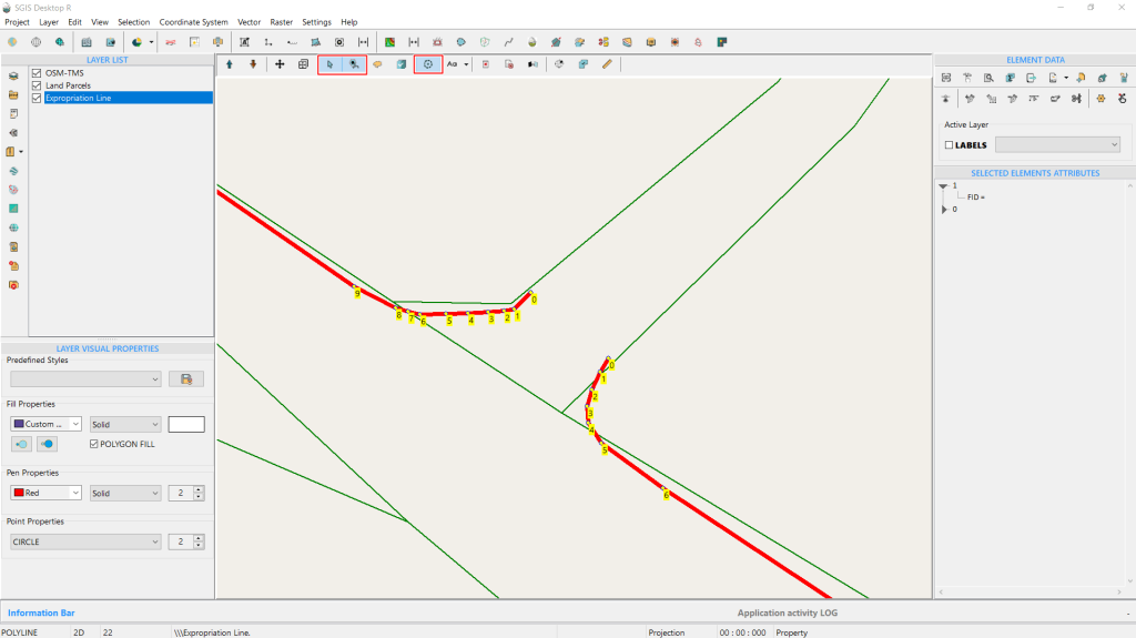
Fig. 2 Zoomed-in view of the area that needs editing for better visual clarity.
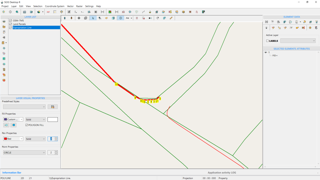
Fig. 3 The selected polyline with vertices displayed in their drawing order.
Fig. 4 Both polylines are displayed and highlighted for better visual clarity. The drawing order of the polylines is clearly visible through the sequence of their vertices.
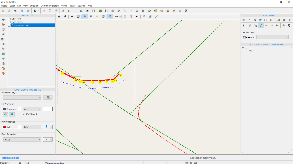
Using the ‘Add to Selection’ Tool, we’ve selected both polylines and displayed their vertices. This highlights the drawing order of each polyline and reveals the gap that needs fixing.
Notably, the first polyline is drawn in a clockwise (CW) order, while the second, lower polyline is in a counterclockwise (CCW) order. We need to adjust the vertex orientation of the first polyline to match the CCW direction of the second one.
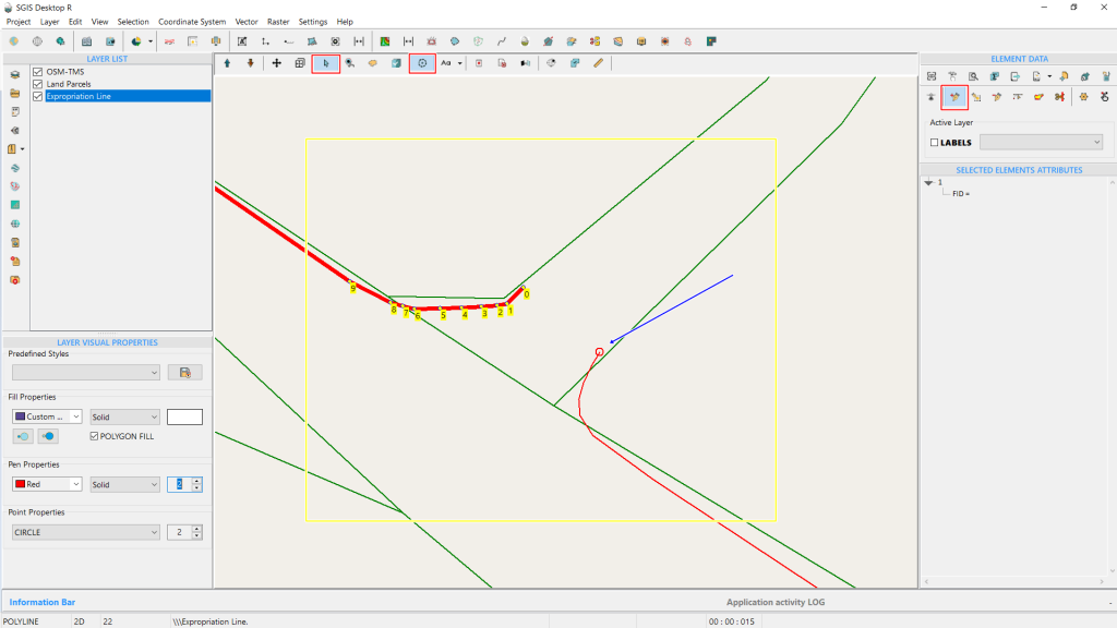
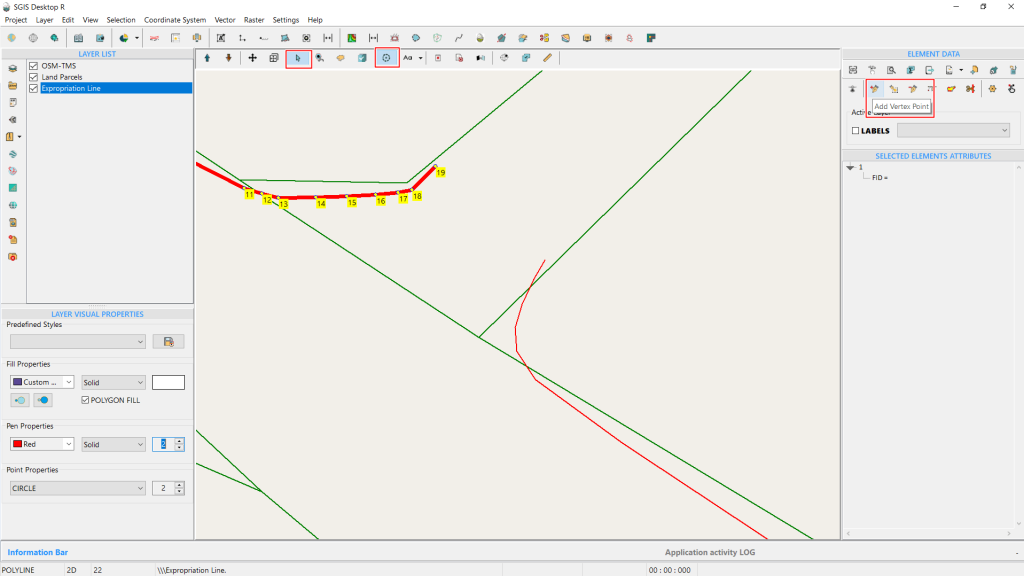
Fig. 5 The red squares highlight the activated 'Selection' and 'Add to Selection' tools. These tools are used before adding a new vertex to visually display both features and pinpoint the exact location for the new vertex. This step is part of the initial procedure to visually merge the two polylines into a single feature.
From the Element Data, we access the editing toolbox and select the ‘Add Vertex’ tool. By holding down the Shift key, we activate the snapping option, which is indicated by a red circle around the desired vertex location. The blue arrow pointer highlights the exact spot where we will place the new vertex using the snapping feature.
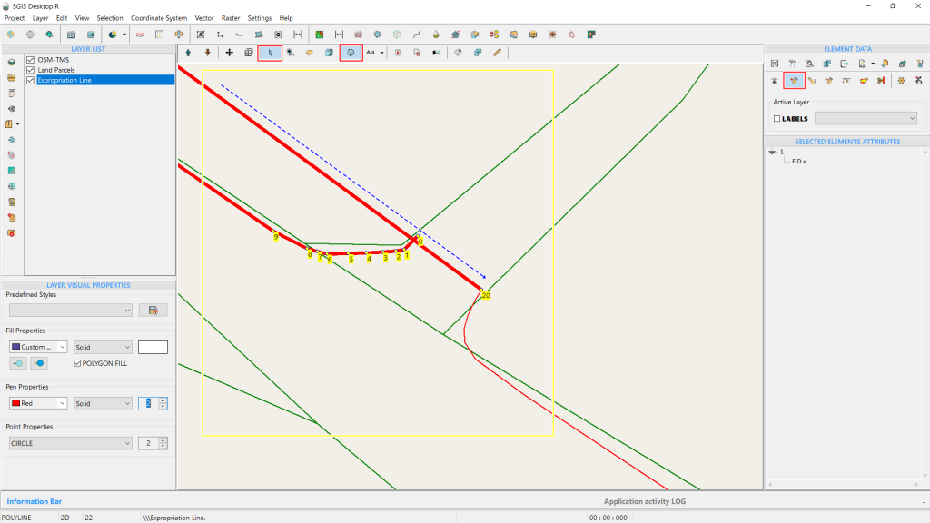
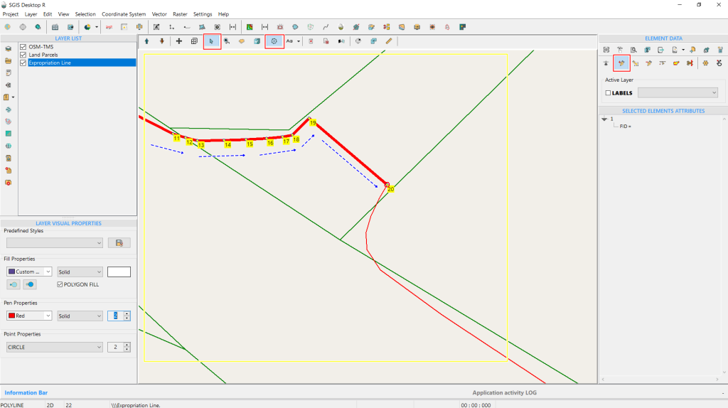
Fig. 6 Using the snapping tool, we place a new vertex at the location highlighted by the blue arrow pointer.
Upon clicking, the new vertex is immediately added. However, since the drawing order is clockwise (CW), the new vertex, numbered 20, connects to vertex 19, which is the last vertex on the upper side.
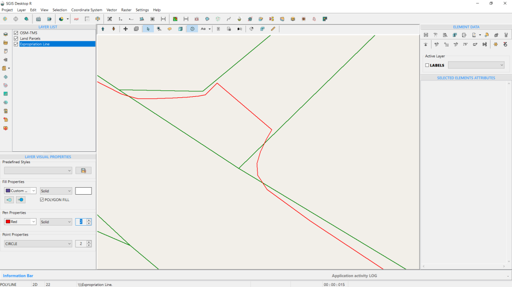
Fig. 7 The clockwise (CW) polyline results in irregular line connection.
As a result, the line is connected irregularly, visually appearing as if it passes through the polyline feature.
Fig. 8 The blue circles highlight vertex 19 and the newly added vertex 20, with the blue arrow indicating the segment's direction after clicking on the point.
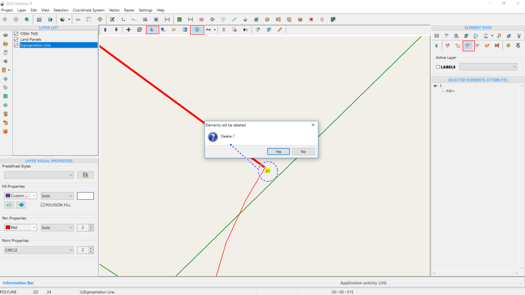
Fig. 9 Deleting vertex 20 using the ‘Delete Vertex’ tool.
Since this is not the desired outcome, we’ll use the ‘Delete Vertex’ tool from the Editing Toolbox to remove the vertex. The command prompts a confirmation, and we click ‘Yes.’ The procedure is completed, and vertex 20 is deleted.
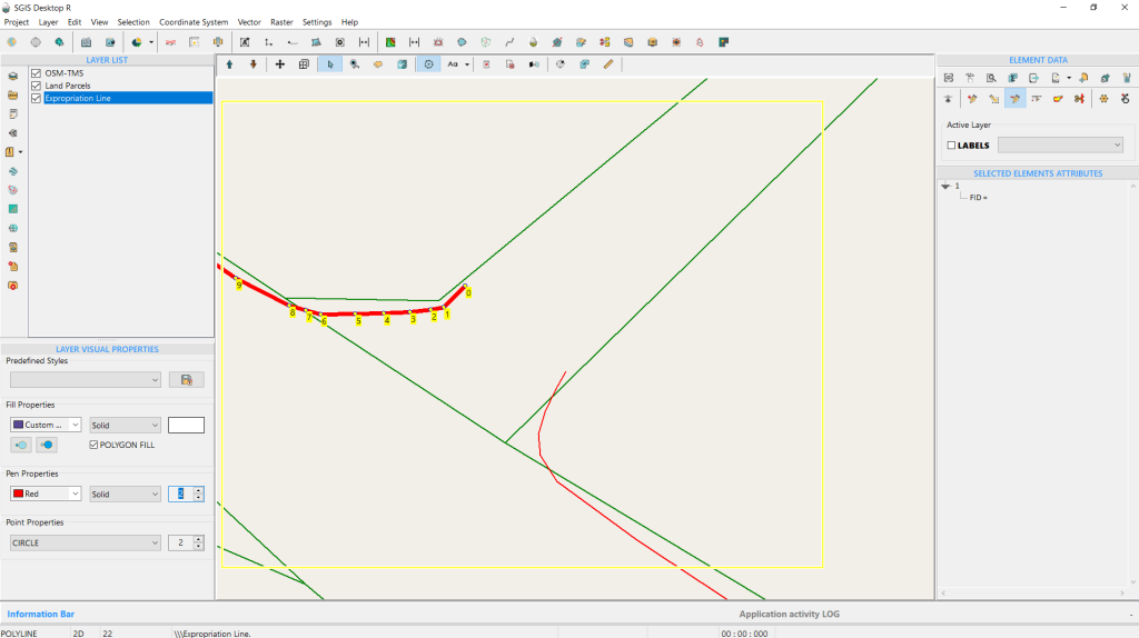
Fig. 10 The procedure is complete.
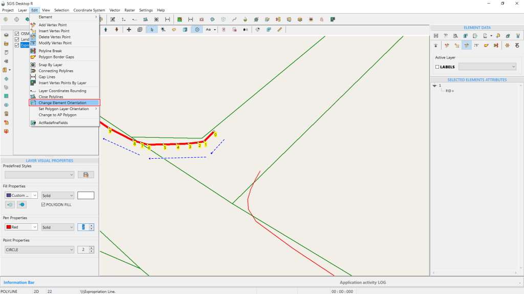
The next step is to open the ‘Change Element Orientation’ function, found in the Edit menu on the Main Menu toolbox. For better visual clarity, it’s highlighted with a red square. On the graphics panel, blue arrows indicate the vertices and their direction before the change.
To begin the process, simply click the ‘Change Element Orientation’ button with the left mouse button.
Fig. 11 Initiating the change of vertex direction from CW to CCW by opening the ‘Change Element Orientation’ function.
Fig. 12 The procedure is complete, and the vertices are now oriented counterclockwise (CCW) as required.
With a single left-click on the function, the procedure is automatically completed. As shown in Fig. 12, the vertices are reordered in the direction indicated by the blue arrows, now in a counterclockwise (CCW) orientation. Note that we need the CCW orientation in this specific example to proceed with the merging process of both lines.
Fig. 13 Using the ‘Add Vertex’ function to extend the polyline.
Whether you should use a CW or CCW orientation in GIS depends on the specific application and the rules governing the data, as well as the specific requirements of the GIS project you are working on. There isn’t a universal rule that CW is more accurate; it is about following the correct orientation as per the data standards you are using.
Fig.14 New vertex added and polyline extended, with direction indicated by blue arrows.
By clicking on the desired vertex and holding the Shift key to activate the snapping option, we place the new vertex accurately. The line is now correctly extended since the vertices are in the proper order. In Fig. 14, this is further highlighted with blue arrows indicating the direction of the polyline.
Fig.15 The procedure is complete.
The procedure is now complete.
A Practical Example #2
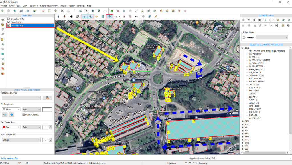
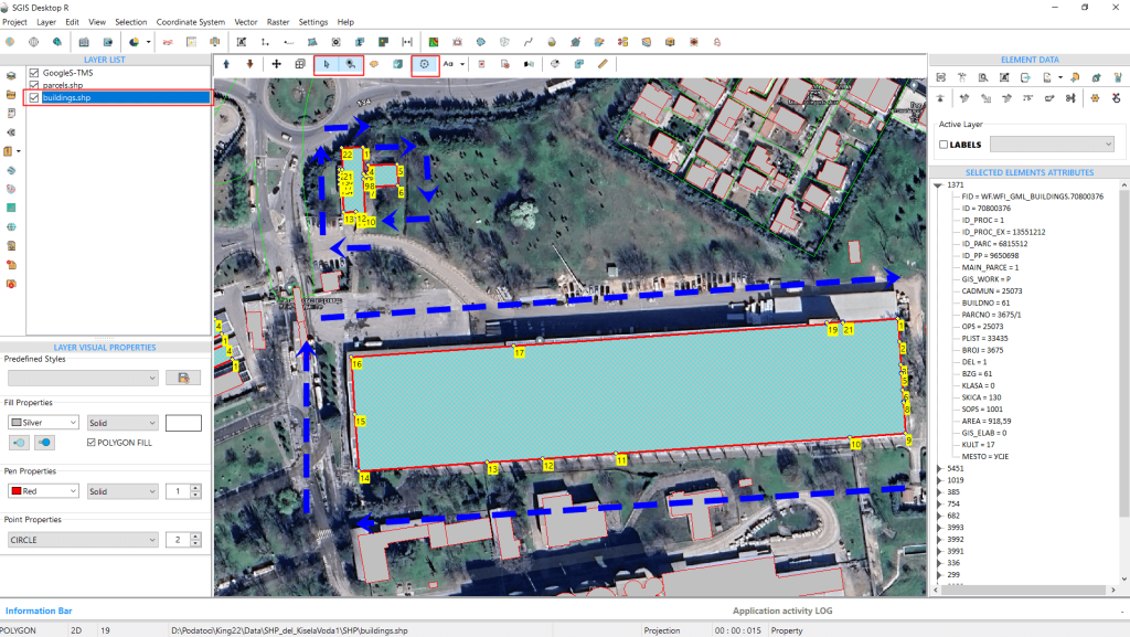
Fig.16 Selected polygons from the building layer, showcasing their current clockwise (CW) vertex orientation before applying the orientation change function.
In this example, we’ll start by opening a SHP file that contains two polygon layers: parcels and buildings. Using the ‘Select’ function along with ‘Add to Selection,’ we select several polygons.
It’s important to note that we’re selecting them purely for demonstration purposes, to show how the vertices look before and after the orientation change. The function itself works on the entire layer, so there’s no need to select individual objects or features. The user only needs to ensure the layer is active in the Layers panel, then open and execute the function.
Returning to our example, as seen in Fig. 16, the orientation of the selected polygon vertices is currently clockwise (CW). Our goal is to change the orientation of all features in this layer—specifically, all the buildings—to counterclockwise (CCW).
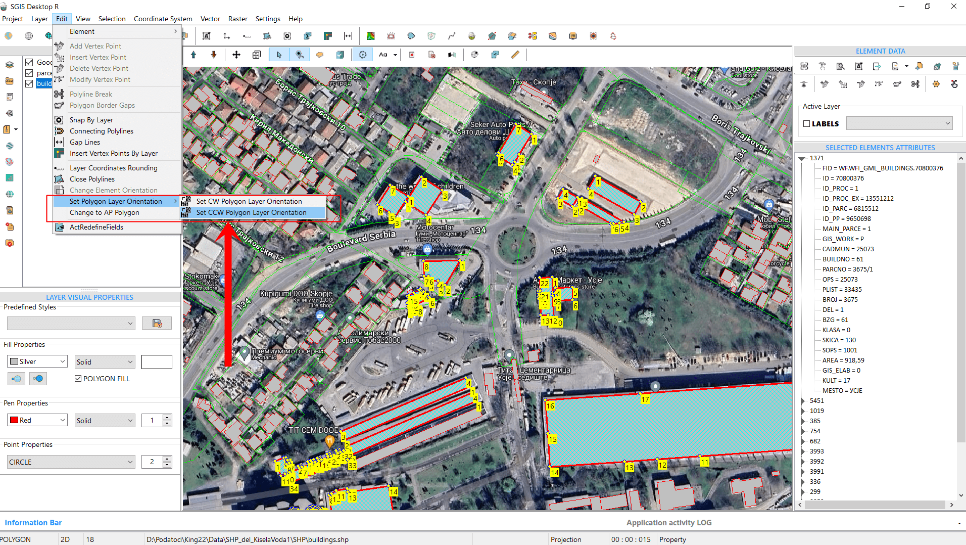
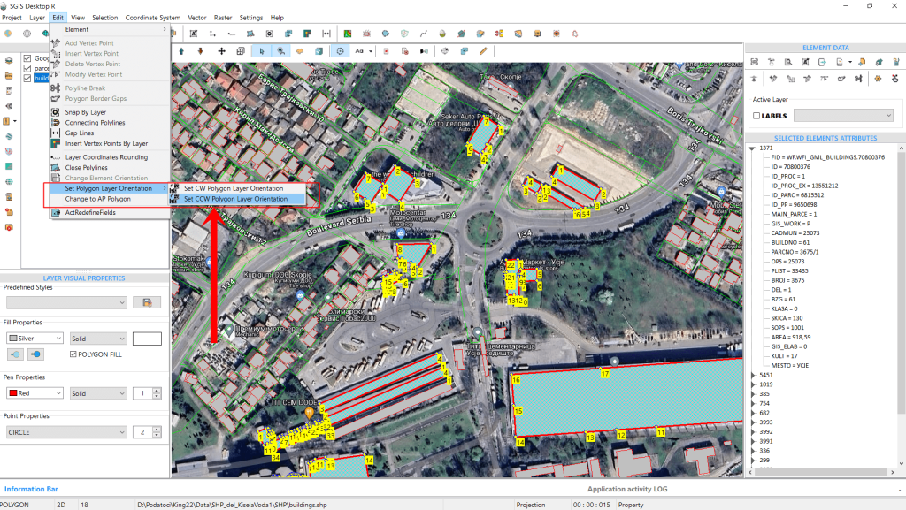
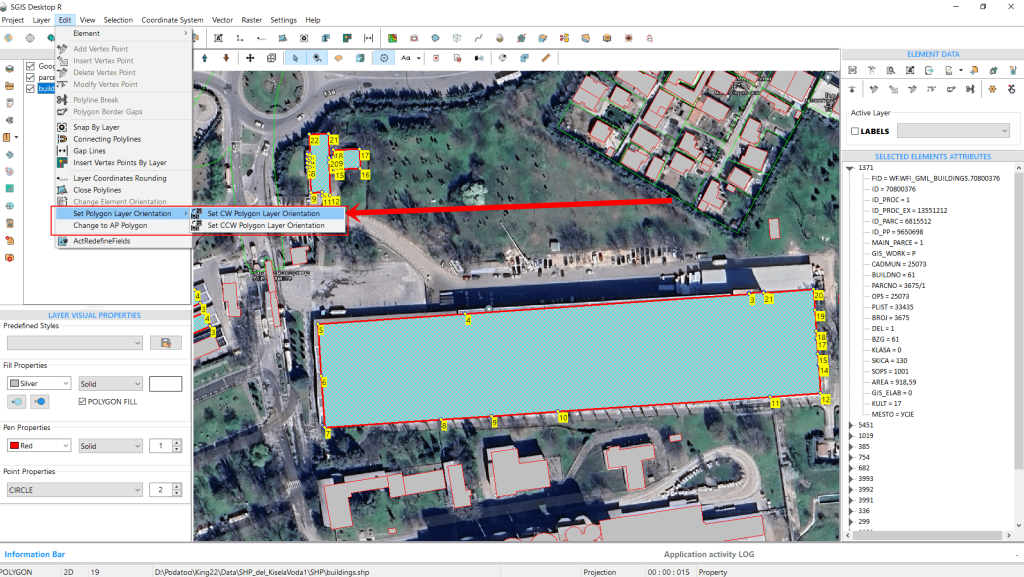
This function provides two options: ‘Set CW Layer Orientation’ and ‘Set CCW Layer Orientation.’ These options standardize the orientation of the entire layer. For instance, if a layer contains polygons with mixed orientations, the function will unify them, making all polygons either CW or CCW, depending on the option selected.
To change the orientation of our SHP layer to CCW, simply click on ‘Set CCW Polygon Layer Orientation,’ and the entire layer will be adjusted accordingly.
Fig.17 Adjusting the polygon layer orientation to counterclockwise (CCW) by clicking on the ‘Set CCW Polygon Layer Orientation’ option.
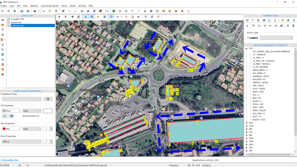
This automatically changes the entire layer to a CCW orientation.
Fig.18 The polygons within the layer have been successfully adjusted to a CCW orientation, reflecting the change across the entire layer.
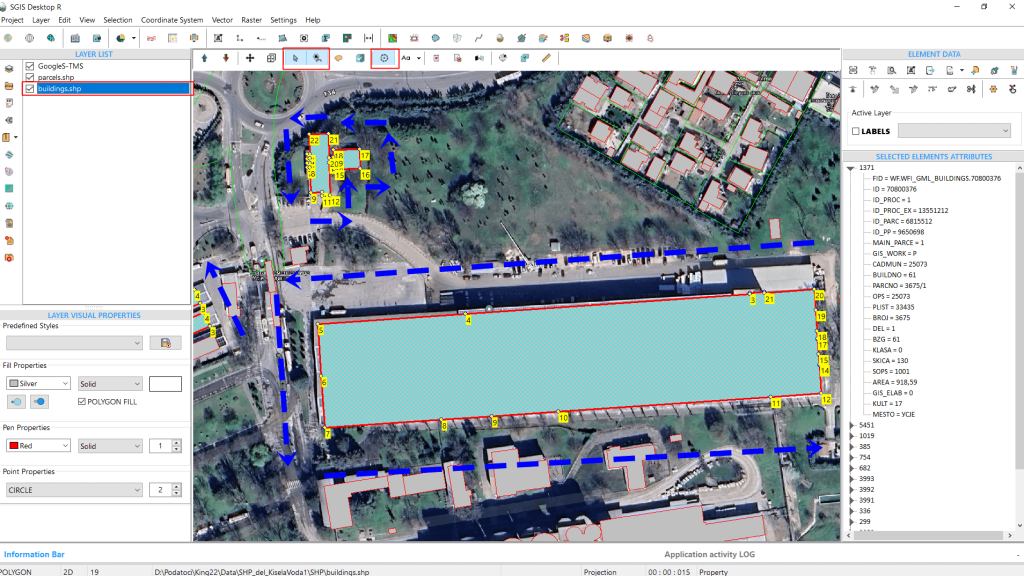
Fig.19 Zoomed-in view showing the polygon layer before reorienting it from CCW to CW, highlighting the vertex points for clearer visualization.
If we need to change the orientation of the entire polygon layer back from CCW to CW, we can easily do so by selecting the ‘Set CW Layer Orientation’ option from the edit menu. With just one click, the layer’s orientation will be adjusted.
In Fig.19, we’ve zoomed in to provide a clearer view of the vertex points for better visualization.
Fig.20 Selecting the ‘Set CW Layer Orientation’ option from the Edit menu.
Fig.21 Zoomed-in view showing the polygon layer after reorienting it from CCW to CW, highlighting the vertex points for clearer visualization.
As mentioned earlier, the SHP file format typically requires the outer boundaries of polygons to have a CW orientation, while the GML file format specifies that these boundaries should be in a CCW orientation.
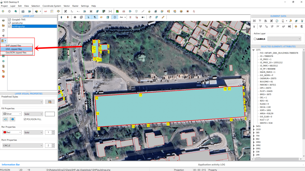
To demonstrate this, we’ll import a GML file from a GML zip archive containing polygons, and then verify and adjust the orientation of the entire layer, switching from CCW to CW and vice versa.
Fig.22 Loading GML data using the ‘Load GML from GML Zip Archive’ function. The polygons displayed are still from the previously loaded SHP files in the Layers Panel list.
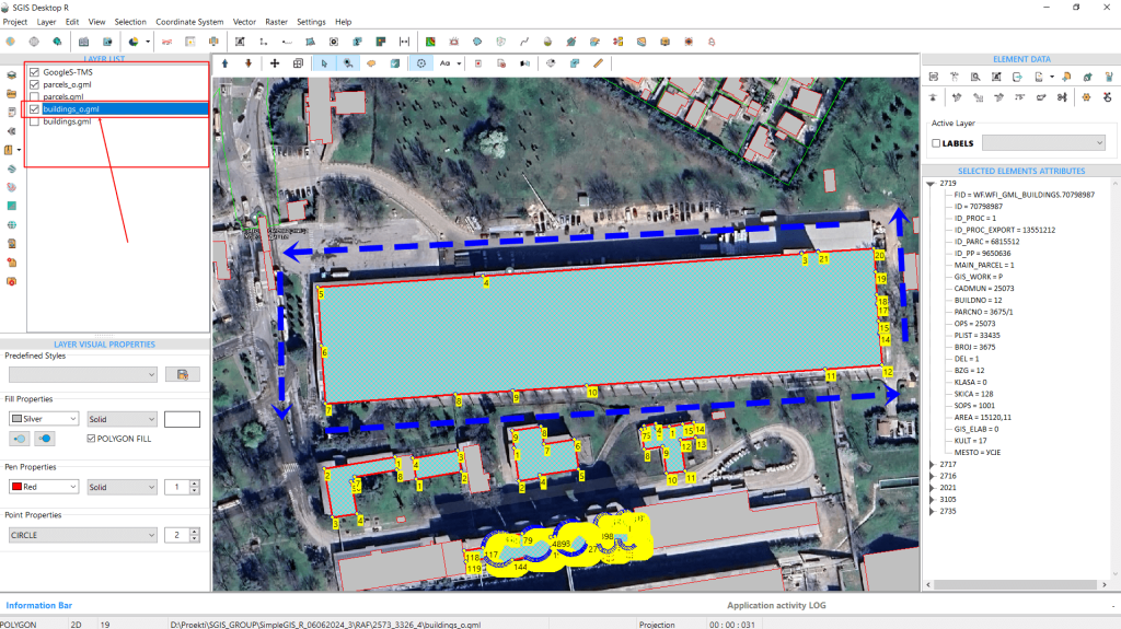
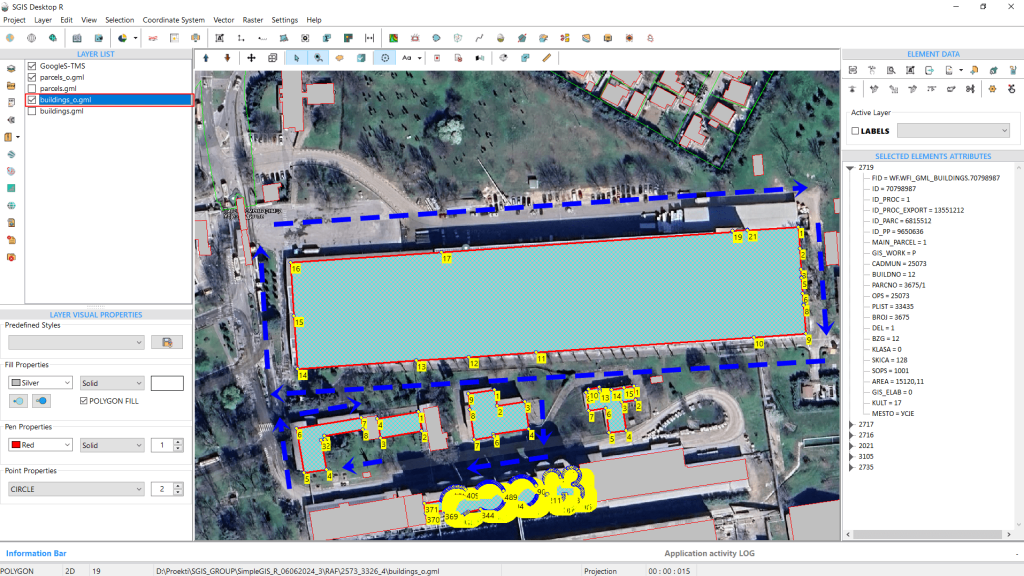
Fig.23 Displaying the vertex numbering for the 'buildings_o' layer, confirming its CCW orientation immediately after loading the GML data.
The GML data has been successfully loaded, containing four GML layers of building and parcel polygons. We’ll focus on the ‘buildings_o’ layer. As shown in Fig.23, after loading the data and enabling the ‘Vertex’ function to display vertex numbering, we can immediately see that the layer’s orientation is CCW.
Using the same function, we’ll now switch the orientation to CW.
Fig.24 Selecting the ‘Set CW Polygon Layer Orientation’ to change the orientation from counterclockwise to clockwise.
Fig.25 The procedure is complete.
The orientation has been adjusted, and the procedure is complete.
It’s important to note that while this function is available for editing, users aren’t required to use it when saving or exporting their SHP files or other formats. During export, the software automatically saves vertices according to the specifications of the file format.