SGIS's Snap by Layer Function: Resnap the Vertices of All Features in One Layer by Using Another Point Layer as the Snapping Condition
Published on: 09.10.2024
This editing task involves adjusting the vertices of features in one layer so that they snap to the points in another layer, using a specific snapping tolerance or condition. By snapping features like lines or polygons to precise points, we ensure that their positions align with more accurate reference data, helping reduce spatial errors. This is especially important when working with datasets from different sources, which often have varying levels of accuracy.
Snapping vertices to a point layer also helps maintain consistency across datasets, which is essential for tasks like overlay analysis, table joins, or building topologically correct models. In networks such as infrastructure, transportation, or utility systems (e.g., roads, pipelines, or cables), snapping ensures that lines connect properly at key points, like intersections or endpoints. This keeps the network intact and enables accurate analysis of connectivity and flow.
For high-precision work—like cadastral mapping or engineering projects—snapping to accurate reference points helps prevent issues with misaligned boundaries or disconnected networks, leading to better decision-making and more reliable results.
To simplify this process, SGIS includes a function that allows users to automatically snap all vertices from one layer to a reference point layer, in addition to manual snapping. This automated cleanup process can significantly reduce the manual effort needed to align large datasets, making data cleaning faster and more productive.
Fig. 1 Demonstrating SGIS automatic snapping function, which aligns vertices from an optical cable network polyline layer with field measurement points.
To demonstrate how effective our snapping function is, let’s walk through a real-world example involving an optical cable network polyline layer and a point layer representing field measurements for network maintenance.
In this scenario, we need to verify the positions of the cable network’s vertices, ensuring that they align with the field measurement points. Although there are additional pipelines within the network, they aren’t shown in this example, which is why you’ll see more points than expected.
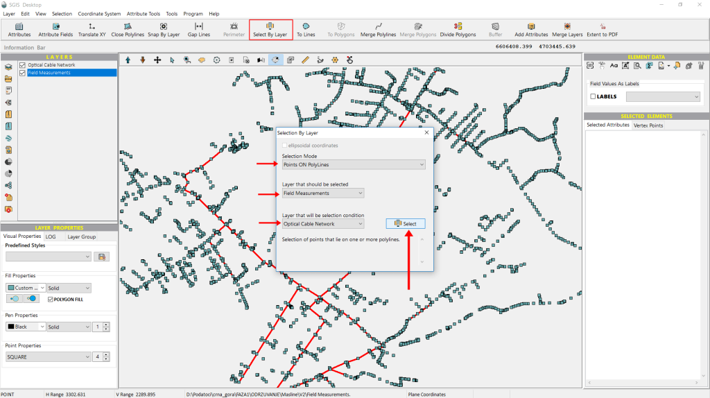
To check if the points and polylines overlap, we’ll use the ‘Select by Layer’ function, which lets us make selections based on a condition layer.
First, we need to choose a ‘Selection Mode’—in this case, we’ll use ‘Points On Polylines’. Next, we’ll select the layer from which we want to filter point data, which will be the ‘Field Data’. Finally, we’ll choose the condition layer, which will be the ‘Optical Cable Network’.
Once that’s done, we simply click ‘Select’ to execute the process and check if the points and polylines coincide.
Fig.2 Demonstrating the Select by Layer function, which identifies overlaps between field measurement points and an optical cable network by selecting points within polylines.
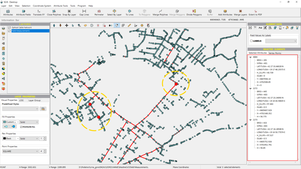
Immediately, the points that meet the specified criteria will be highlighted on the graphics panel.
As shown in Fig.3, only three points meet our criteria.
Since we require all points to precisely overlap with the polylines, specifically, we need the vertices of the polylines to align exactly with the measurement data points. To achieve this, we will utilize the ‘Snap by Layer’ function.
Fig.3 Highlighted points on the graphics panel that meet the specified criteria. Only three points are identified as matching the conditions set for overlap with the optical cable network polylines.
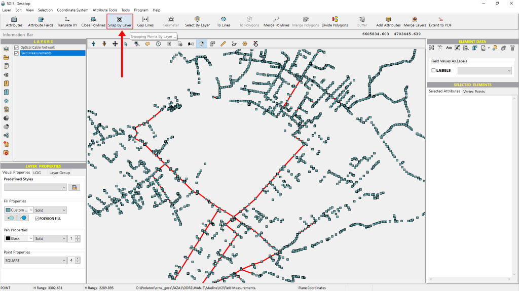
We can find the ‘Snap by Layer’ function on the main toolbar in the user interface. To use it, we just click on the icon.
Fig.4 The ‘Snap by Layer’ function can be activated by clicking the corresponding icon.
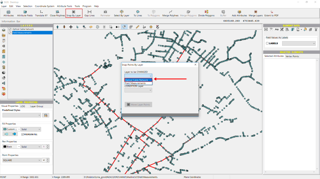
A new dialog window will appear immediately. In this window, we need to specify which layer we want to modify and which one will serve as the condition layer.
Starting with the first dropdown, for ‘Layer to be changed’, we select ‘Optical Cable Network’.
Fig.5 A new dialog window appears where we need to choose, from a dropdown list, which layer will be modified. In this case, the 'Optical Cable Network' layer is selected for modification.
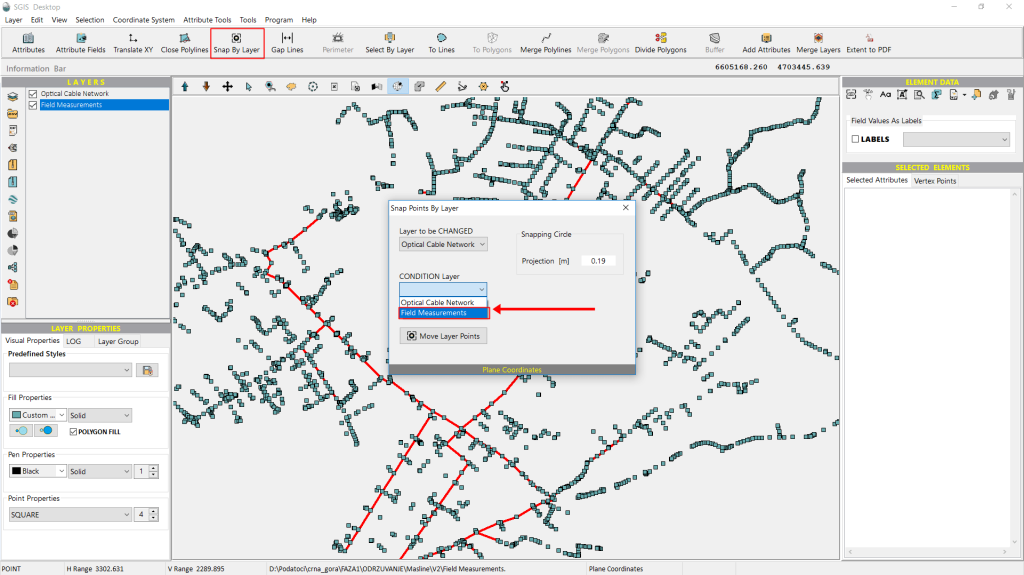
From the ‘Condition Layer’ dropdown list, we select ‘Field Measurements’. This is an easy choice, as there are only two layers loaded in the Layers panel.
Another setting users can adjust based on their needs is the tolerance gap. This option becomes available after selecting the layer to be modified. Since our layer uses a projected reference system in meters, we’ve set the tolerance gap to 0.19 meters, but this value can be adjusted to suit the user’s requirements.
Fig.6 The 'Field Measurements' layer is selected from the Condition Layer dropdown list, given that only two layers are available in the Layers panel.
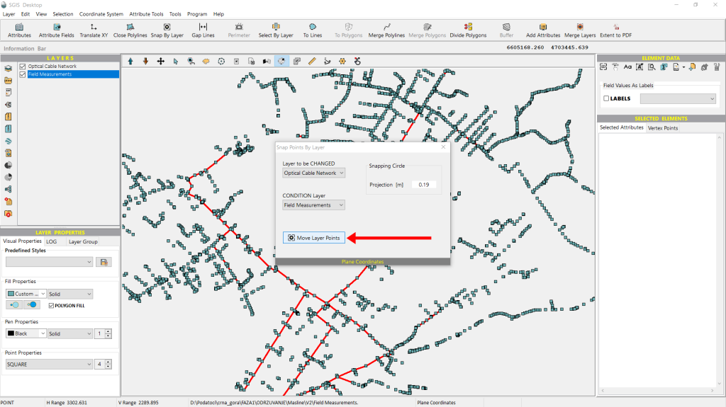
Once all the settings are configured, we simply click on ‘Move Points’ to apply the changes.
Fig.7 After configuring all the settings, the 'Move Points' button is clicked to apply the changes and align the vertices with the condition layer.
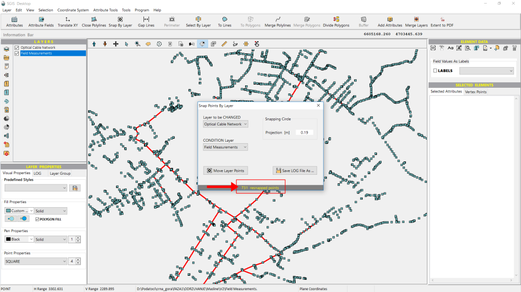
The Info bar at the bottom of the ‘Snap by Layer’ dialog window immediately displays a message indicating how many points have been resnapped.
Fig.8 The Info bar at the bottom of the Snap by Layer dialog window displaying a message with the number of points successfully resnapped.
Now that the procedure is complete and the points have been resnapped in just milliseconds, we can reopen the ‘Select by Layer’ tool to check if the points now align correctly.
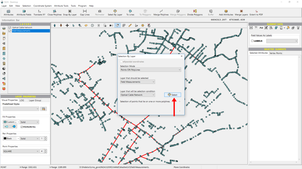
We open the ‘Select by Layer’ dialog, configure the settings just as before, and then click ‘Select’ to proceed.
Fig.9 The Select by Layer dialog is reopened, with the same settings configured as before, followed by clicking the 'Select' button to continue.
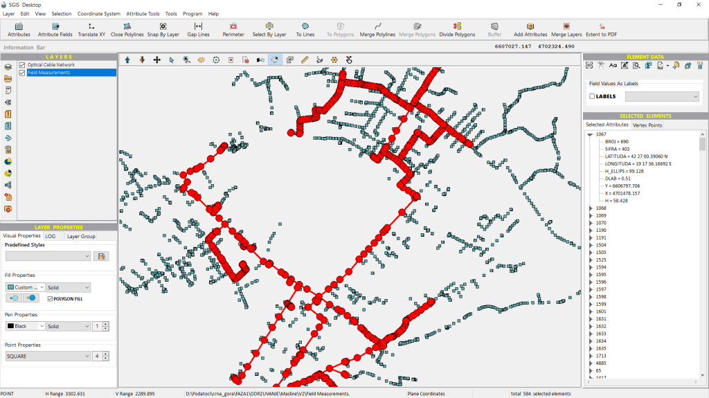
Fig.10 All points are now selected and highlighted in the graphics panel, confirming they align perfectly with the field-measured point data after the resnapping process.
This time, all the points meet the desired criteria and are selected and highlighted in the graphics panel, confirming that they now align perfectly with the field-measured point data after being resnapped.
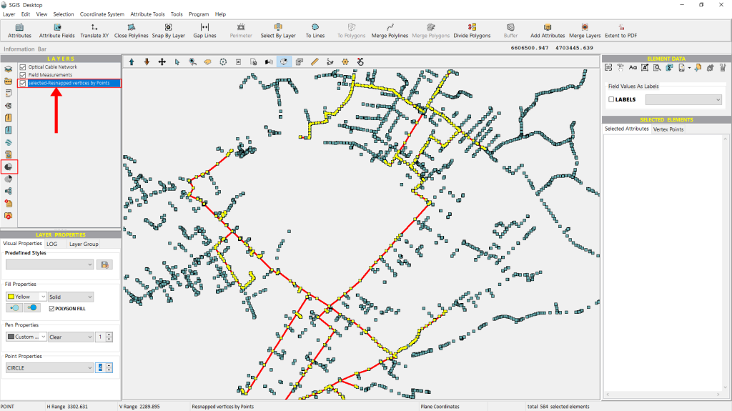
Additionally, we can export these points to separate them from those that may need modification in the future. This is done using the ‘Selected elements in New Layer’ function, a one-click feature that instantly creates a new layer in the Layers panel. This makes the data ready for export or further processing. With this, the procedure is successfully completed.
Fig.11 Using the 'Selected elements in New Layer' function to create a new layer in the Layers panel, allowing the selected points to be exported or further processed separately.